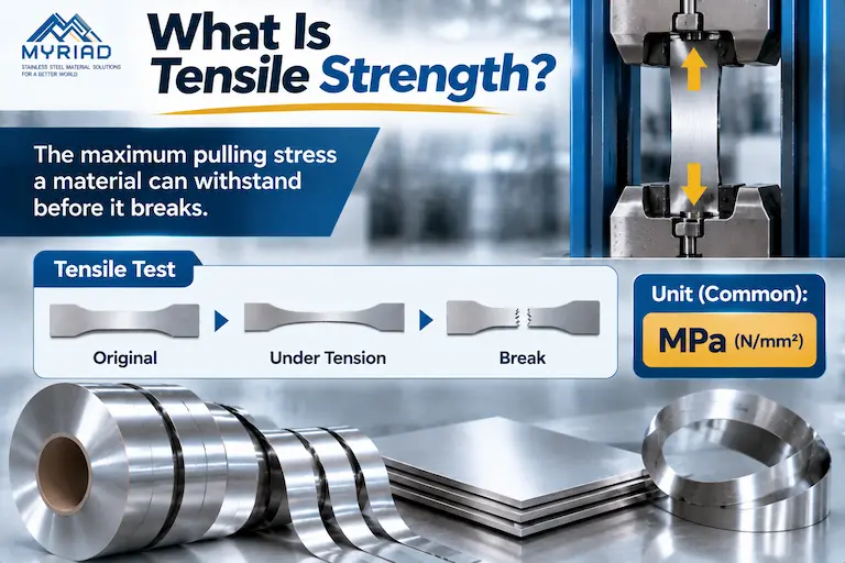

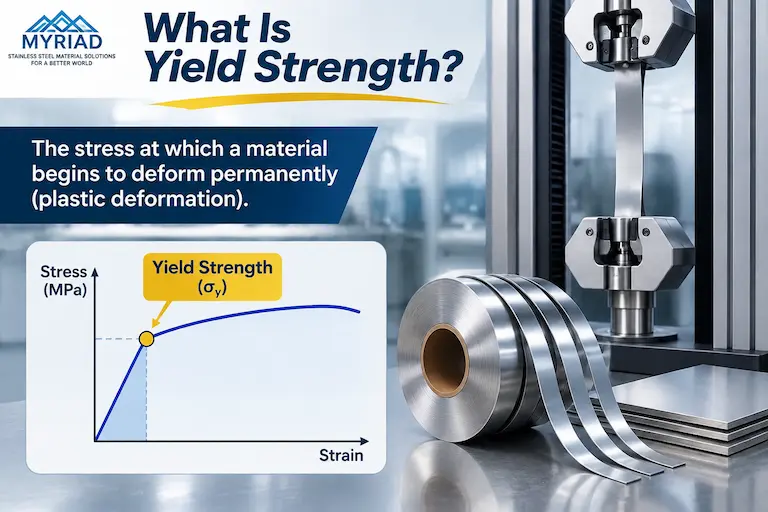
In metal testing, yield strength is a stress value used to describe resistance to permanent deformation under a stated test criterion. A report may identify a distinct yield point or a specified proof stress, such as 0.2% offset yield strength. These are not automatically the exact stress at which the first microscopic plastic deformation begins. Instron’s yield-strength explanation describes both the permanent-deformation meaning and the use of an offset criterion.
To calculate a yield or proof stress, first identify the force that corresponds to the required criterion, then divide it by the specimen’s original cross-sectional area. The area calculation is straightforward; choosing the correct force requires the tensile-test record and method. The maximum force used for ultimate tensile strength is a different input.
What is yield strength used for?
Yield or proof strength helps engineers compare material conditions, check mechanical specifications and assess the tendency toward permanent set. For stainless steel foil used in an elastic function, it is one input when considering whether a part will retain its intended shape after unloading. The public guidance for ASTM E8/E8M identifies material comparison, quality control and acceptance as uses of tensile-test results.
A single yield value does not establish a finished part’s allowable load, fatigue life or forming outcome. Part geometry, loading, temperature and processing conditions also matter. In stainless forming, Outokumpu’s guidance explains that springback depends on the steel and forming conditions; a proof-stress value alone is not a springback-angle prediction.
Yield point, proof stress and elastic limit
The reported symbol tells you which criterion to compare. A material with a distinct yield event may be described by upper and lower yield strengths; a curve without an easily discernible event may instead use a specified offset. ZwickRoell’s yield-point guidance distinguishes these cases.
| Reported quantity | Meaning in the tensile test | Comparison requirement |
|---|---|---|
| Upper yield strength, ReH | Upper yield value before the first significant force drop | Use the method’s upper-yield criterion |
| Lower yield strength, ReL | Lowest stress in the subsequent yielding region, with transient effects treated as specified | Do not interchange it with ReH |
| 0.2% proof stress, Rp0.2 | Stress corresponding to the specified 0.2% non-proportional or plastic extension criterion | Retain the offset value and applicable method |
Proof stress, elastic limit, proportional limit and elastic modulus answer different questions. Elastic limit concerns recoverability; proportional limit concerns the range of proportional stress and strain; elastic modulus, E, describes the slope of the specified elastic portion. An offset proof stress is a reporting convention rather than a precise elastic-limit measurement. Instron’s elastic-limit discussion explains why the elastic and proportional limits need not coincide.
How to calculate yield stress
The engineering stress calculation uses the force selected by the required yield criterion and the original test-section area. In general notation, σy = Fy ÷ S0. For the 0.2% proof criterion, write Rp0.2 = Fp0.2 ÷ S0, where Fp0.2 is the force at the identified proof point. Original cross-section measurement is part of metal tensile testing.
For a rectangular flat specimen, S0 = w0 × t0. Use the original width and thickness in the test section, rather than a necked area near fracture. A force divided by mm² gives N/mm², which equals MPa. If the force has not been identified by the specified criterion, dividing it by an accurate area still does not make it a valid yield result.
Hypothetical flat-specimen example
Assume an original width of 8 mm, a thickness of 0.10 mm, and a force of 240 N already identified from the 0.2% offset criterion. These are teaching inputs, not a Myriad material test, grade guarantee or prescribed standard specimen size.
| Step | Calculation or result |
|---|---|
| Original area | 8 mm × 0.10 mm = 0.80 mm² |
| Identified proof force | Fp0.2 = 240 N |
| Proof stress | 240 N ÷ 0.80 mm² = 300 MPa |
| Same stress in US customary units | Approximately 43.5 ksi |
MPa and ksi express the same stress quantity in different units. The NIST conversion table gives the basis for 1 ksi ≈ 6.894757 MPa. This unit conversion does not change a tensile-strength result into a yield-strength result.
How the 0.2% offset method finds proof stress
The offset method locates a defined point on a measured stress–strain curve. It requires usable strain data as well as force data; it cannot be reconstructed from maximum force alone. Instron’s offset-yield explanation describes the intersection with a line parallel to the specified elastic-modulus line.
- Obtain the tensile-test force and specimen-strain record under the applicable method.
- Determine the relevant initial elastic slope using that method’s procedure.
- Offset a parallel line along the strain axis by 0.002, equivalent to 0.2% strain.
- Find its intersection with the measured curve and report the corresponding proof stress, or use the corresponding force and original area.
In an idealized plot with the zero corrected and the fitted elastic line passing through the origin, the offset line can be written σoffset = E × (ε − 0.002). Here ε is strain as a dimensionless decimal, and E must use the same stress unit as σ. This is the geometry of the offset line, not a material law for the whole curve or a substitute for the specified test procedure.
The 0.2% offset is neither 0.2% of UTS nor necessarily the total strain at the intersection. The measured total strain there also includes elastic extension. Other offsets may be specified, and Rp0.2 should not be treated as a guarantee of absolutely zero plastic deformation at every lower stress.
Yield strength vs. tensile strength
Yield or proof strength uses a defined deformation criterion; ultimate tensile strength, UTS or Rm, uses the test method’s definition of maximum tensile force. The denominator can be the same original area while the force in the numerator is different. ZwickRoell’s tensile-strength explanation gives Rm = Fm ÷ S0 and describes method-specific maximum-force treatment.
For the same hypothetical 0.80 mm² specimen, a method-defined maximum force of 480 N would give Rm = 480 ÷ 0.80 = 600 MPa, approximately 87.0 ksi. The proof result remains the separately identified 300 MPa. Knowing 480 N or 600 MPa alone would not have supplied the 240 N proof force; the two example values do not establish a conversion ratio.
What changes a stainless steel yield result?
A stainless steel grade does not have one yield value independent of condition. Check the delivery condition and applicable product specification alongside the material designation; the stainless steel grades guide helps identify the material family. The 304 coil properties and testing guide provides related specification context.
Knowledge-base evidence illustrates why the measured properties should stay distinct. Li Zhifeng’s 2014 study of cold-rolled SUS301 and SUS304 strip, consulted through Myriad’s knowledge base, reports yield strength and tensile strength from tensile testing, with separate micro-Vickers hardness measurements. That method record does not supply a universal hardness-to-yield calibration or a fixed yield-to-tensile ratio, and it is third-party research rather than Myriad’s own experiment.
Compare like conditions when evaluating a material report or requesting 301 stainless steel foil and thin sheet. Keep the grade, condition, sampling orientation, thickness, temperature, strain-rate or test-rate conditions, method and proof criterion identifiable. A change of grade name alone does not explain all differences between reported values.
Why foil testing needs reliable strain measurement
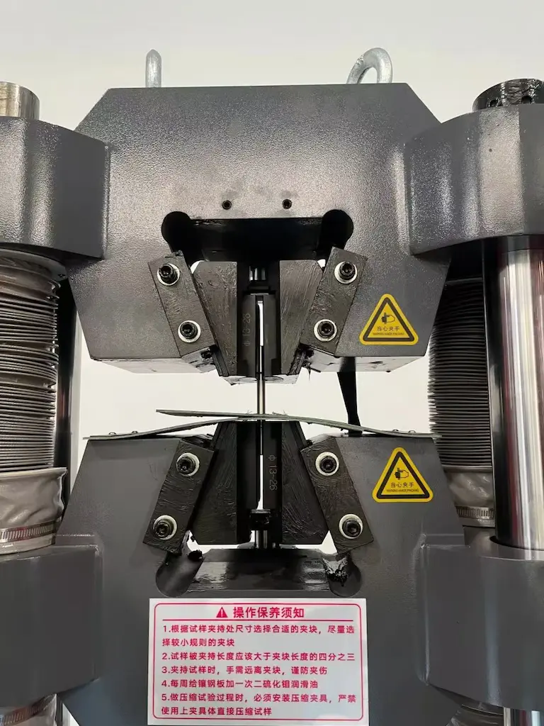
Thin foil makes both cross-section measurement and strain measurement consequential. Thickness error changes the stress calculated from force; an unsuitable strain record can change where the proof point is identified. Specimen edges, creases, alignment and grip slippage also require attention. ZwickRoell’s metallic-foil guidance specifically identifies extensometer-based strain measurement for Rp0.2 determination.
Agree the appropriate method and measurement arrangement with the laboratory and purchasing specification. ASTM E345-24a addresses metallic foil, while ISO 6892-1 covers room-temperature tensile testing of metals. E345’s public guidance does not define one foil-thickness boundary for all alloys. Permission to use grip separation for certain elongation measurements should not automatically be transferred to Rp0.2 determination or interpreted as permission to substitute crosshead travel for specimen strain.
Can hardness or tensile strength give yield strength?
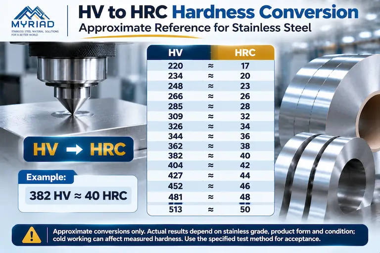
An empirical correlation needs evidence for the material and conditions being assessed. Hardness, UTS and yield or proof stress are different measurements or reported properties. A VTT research-report abstract on hardness and strength correlations identifies material and strain-hardening conditions that affect the relationship. A universal fraction of UTS or a universal HV coefficient is not a justified yield calculation for stainless steel foil.
The current Myriad hardness and tensile strength calculator is useful for a separate hardness–UTS reference comparison. Its current inputs and outputs cover hardness scales and tensile Rm in MPa or ksi; it does not calculate yield strength or Rp0.2. Do not enter a yield value in its tensile-strength field and relabel the result as yield. Use the specified test result for a yield requirement, or obtain explicitly applicable, validated correlation data where that route is permitted.
Prepare a clear foil specification
Myriad supplies stainless steel foil and precision strip, with the requested material combination reviewed for the order. Submit the grade, delivery condition, thickness, width, quantity and required mechanical-property criterion. Include applicable sampling, testing and reporting requirements; for width and edge needs, see Myriad coil slitting. If the performance target is undecided, provide the relevant application conditions for a selection discussion.
Smaller-quantity requests can be reviewed individually. Myriad’s standard minimum is 100 kg per specification item within one order, defined by the same grade, thickness, width and material condition; lower quantities require a separate application.
For an additional hardness or tensile-reference comparison, open the calculator and retain the source measurement and its property name. Yield or proof requirements remain separate.
Technical sources and method
This guide uses published testing guidance, public standards scope statements and a knowledge-base research source. The knowledge-base reference is Li Zhifeng, 冷轧SUS301和SUS304不锈钢带材的板形及力学性能研究 (2014), used for the reported distinction between tensile outputs and separate hardness testing. The original thesis formulas and numerical models were not adopted as a general yield calculation.
The numerical specimen example is hypothetical. The Myriad calculator’s public HTML and current implementation, version 0.3.2, were checked on November 7, 2026 for their stated property scope; no new browser conversion trial or material test was performed for this article. Paid standards procedures and the full VTT report were not reviewed. The method explanation is not a complete laboratory procedure or finished-part design verification.